Turbidimeter system prevents shutdowns |
|||||||
|
|
Model AP-VIE Indicator/ControllerA Model AP-VIE Indicator/Controller used for maintaining proper concentration levels as a sulfur dioxide plant through an in-pipe effluent stream to provide continuous real-time turbidity measurement. |
||||||
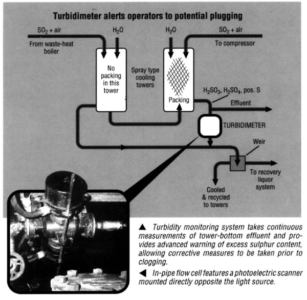
ProblemA Virginia-based chemical producer was being forced to shut down its sulfur dioxide production one day each month to clean a cooling tower that would clog with sulfur particles created by incomplete sulfur burning. To produce S02, the company combines sulfur and air in a burner. The resultant stream is then transferred to a cooling tower where it is sprayed with water, and then to another water-spraying cooling tower with packing. From here, the effluent is removed to recovery systems and the SO2 stream is transferred to a compressor. The clogging problem would arise when excess sulfur entered the burner. Typically, this would happen when: 1) excessively moist air was pumped into the burner, 2) the compressor drawing air into the burner was operating inefficiently, 3) over-heated molten sulfur's lower viscosity would cause excess sulfur input, or 4) the sulfur pump and/or its controls were malfunctioning. When too much sulfur was in the system, excess sulfur vapor would desublime back into particulate matter as it passed through the cooling tower~ Some sulfur particles would collect with-in the packing of the second tower, while the rest would settle in the tower-bottom effluent stream, giving it a milky appearance. By the time the tower-bottom effluent turbidity was visually evident it was too late for preventative action, as the packing would already be so clogged that compressor vacuum would increase and throughput decrease, causing production bottlenecks and system-cleaning shutdowns. SolutionAn in-pipe sensitive turbidimeter was installed in the tower-bottom's effluent stream to provide continuous real-time turbidity measurement and alert operators to the presence of excess sulfur before it becomes visually apparent and prior to throughput being affected. The turbidimeter consists of a flow cell, light source and photo-electric scanner. Electronic signals are sent from the turbidimeter to the cabinet containing an indicator/monitor and an alarm relay. The light source is mounted on the effluent stream's 1 - 1/2-inch-diameter stainless steel flow cell. Mounted directly opposite is the photoelectric scanner. Changes in the amount of suspended solids within the effluent change the amount of transmitted light received by the photoelectric scanner. The electronic signal transmitted by the scanner to the monitor varies in direct proportion to the solids contained. In this application, the readout of relative turbidity is in parts-per-million (ppm). To calibrate the turbidimeter, a reference stream is passed through the line containing a known amount of solids, 5-10 ppm of entrained solids on the APHA scale. The monitor is set to read zero when the reference stream is passed through the flow cell. The scale of the meter is graduated from 0-100, where 100 represents suspended solids content of 200 ppm. The turbidimeter is set to continuously monitor the solids in the effluent stream. Calculations indicated that when the effluent stream contained more than 50 ppm of sulfur particles, clogging in the cooling tower would commence, so a relay-trip was established at this 25% relative turbidity level. At that level of solids concentration, turbidimeter signals activate the alarm relay. The alarm alerts operators that excess sulfur is entering the burner and allows them to adjust sulfur input to compensate for moist air, adjust the temperature of the burner, or repair the compressor or pump controls. These adjustments served to maximize throughput and eliminate the need for monthly shutdowns for tower cleaning. Questions? Contact McNab A92-40BLegal Notice: This document may not be used, other than for reference on www.themcnab.com, under penalty of law. |
|||||||
|
|||||||